สินค้า
ROF (72-550) kV
รายละเอียด
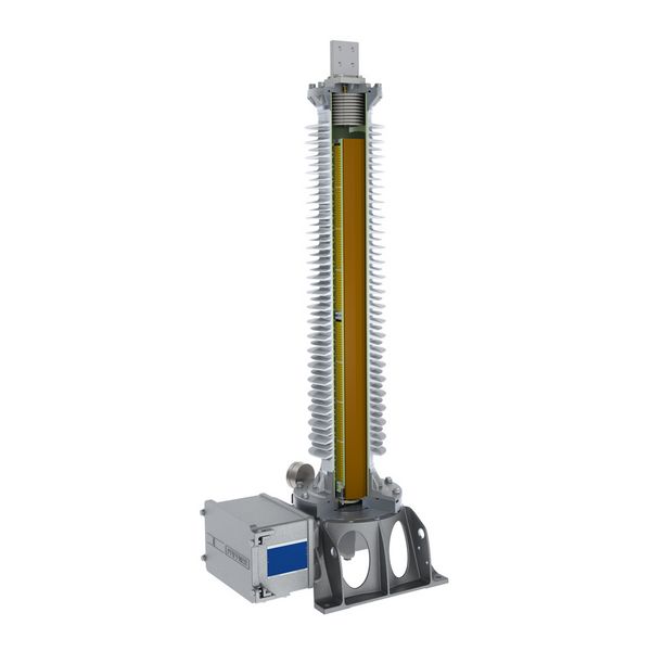
RC DIVIDERS | OUTDOOR OPERATION
- Oil insulated
- Protection and measurement in high-voltage transmission
- Can be used for the measurement of mains quality
- Highest accuracy from DC up to 10 kHz
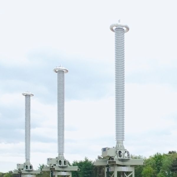
Resistive capacitive voltage dividers type ROF (RC divider) are used in high voltage networks within the 72.5-550 kV range. They divide the primary voltage into a standardised, equivalent secondary voltage for meters, measuring and protection devices.
GENERAL DESCRIPTION
Resistive capacitive voltage dividers type ROF (RC divider) are used in high voltage networks within the 72.5-550 kV range. They divide the primary voltage into a standardised, equivalent secondary voltage for meters, measuring and protection devices.
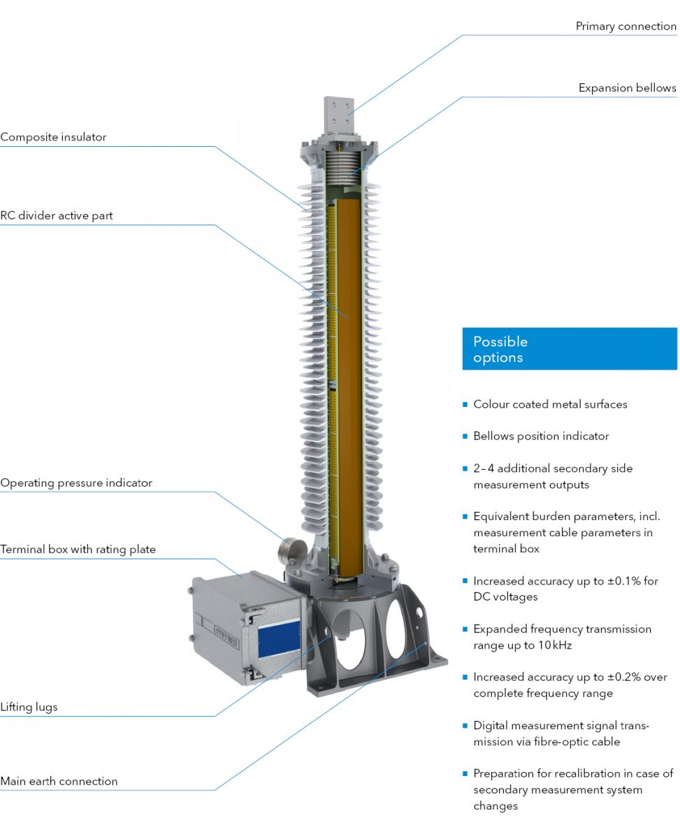
The active part of the RC divider consists of a capacitor divider and a parallel connected resistor divider. The length of the active part extends along the entire insulator length, which results in an excellent linear voltage distribution. Both dividers are matched with each other and reflect the transient voltage signals from the high voltage side precisely on the low voltage side. Due to the internal structure, an RC divider can be used for various frequencies and to measure alternating and direct voltages.
As the active part of the RC divider is hermetically sealed to the outside, an expansion bellows in the head section compensates volume changes in the impregnation oil due to temperature variations. The operating pressure can be visualised via a manometer or a bellows position indicator.
To avoid field distortions, a shielding electrode is used in the divider head for voltage levels of 420 kV and above.
The secondary elements are located in the generously designed terminal box. In addition to fine adjustment and fast overvoltage protection, the terminal box also includes equivalent burden parameters. The terminal box cover is opened laterally and is fixed to the terminal box.
The transmission of the secondary voltage can be implemented either as analogue signal via a shielded measurement cable or as a digital signal via a fibre-optic cable.
The RC dividers are normally factory calibrated and can be put directly into operation.
Advantages of capacitive
resistive voltage dividers
- Ferroresonance-free and no saturation effects
- Secondary output operates without problems under short-circuit or no-load conditions
- AC accuracy class ±0.1% @ fN
- Measurement of harmonics possible up to 1 MHz
- Accuracy with harmonics up to 10 kHz of ±0.2%
HIGHLIGHTS

Linear
voltage distribution
- The optimised arrangement of the R and C dividers across the entire insulator length results in excellent voltage distribution.
- The RC divider shows a perfect performance under transient voltage loads and high pollution risk.
- The homogeneous field distribution prevents the occurrence of external partial discharges.

High accuracy at
frequencies up to 10 kHz
- The specially developed design of the active part with the resistor and capacitor components enables a very high measurement accuracy and stability up to the 200th harmonic of the rated system frequency.
- At the same time, high accuracy and stability in voltage variation (linearity) is achieved, starting with just a few percent of UR up to the overvoltage factor.

Simple measurement
cable connection
- The terminal box has a base with connection sockets. The specially prepared measurement cable can be connected here easily without opening the terminal box.
- If the number of measurement cables is increased, an additional cable can be plugged into the next terminal. To do this, the prepared burden indicator must be switched off with a switch in the terminal box. The divider is then equalised and ready for operation again.
DESIGN
TECHNICAL DATA

| Type ROF | 72 | 123 | 145 | 170 | 245 | 362 | 420 | 550 | ||
|---|---|---|---|---|---|---|---|---|---|---|
| Standard | IEC / IEEE | |||||||||
| Highest voltage for equipment | kV | 72.5 | 123 | 145 | 170 | 245 | 362 | 420 | 550 | |
| Rated power-frequency withstand voltage | kV | 140 | 230 | 275 | 325 | 460 | 510 | 630 | 680 | |
| Rated lightning impulse withstand voltage | kV | 325 | 550 | 650 | 750 | 1050 | 1175 | 1425 | 1550 | |
| Frequency | Hz | 16.7 / 50 / 60 | ||||||||
| Accuracy class | 0.1; 0.2; 0.5; 1.0; 3.0 | |||||||||
| Expanded frequency band | Hz | 15 - 10000 | ||||||||
| Burden | R or R//C | |||||||||
| Burden range | ≥ 100 kΩ | |||||||||
| Rated voltage factors | VF | 1.5 - 30 sec / 1.9 - 30 sec / 1.9 - 8 h | ||||||||
| Type ROF | 72 | 123 | 145 | 170 | 245 | 362 | 420 | 550 | ||
| Height of unit* | A | mm | 1306 | 1606 | 1806 | 2006 | 2606 | 3371 | 3771 | 4571 |
| Height to primary terminal* | B | mm | 1186 | 1486 | 1686 | 1886 | 2486 | 3491 | 3891 | 4691 |
| Depth of unit including terminal box | C | mm | 724 | 724 | 724 | 724 | 724 | 724 | 724 | 724 |
| Depth of unit base | D | mm | 500 | 500 | 500 | 500 | 500 | 500 | 500 | 500 |
| Width of unit base | E | mm | 500 | 500 | 500 | 500 | 500 | 500 | 500 | 500 |
| Distance between screw holes at base | F | mm | 450 | 450 | 450 | 450 | 450 | 450 | 450 | 450 |
| Min. creepage distance* | mm | 2420 | 3540 | 4280 | 5030 | 7260 | 9414 | 11720 | 14314 | |
| Approximate weight* | kg | 100 | 125 | 140 | 155 | 200 | 230 | 250 | 340 | |
*with standard composite silicone insulator, creepage distance 25 mm/kV