

EJGF (245-550) kV
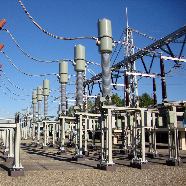
COMBINED TRANSFORMERS | OUTDOOR OPERATION
- SF6-gas insulated
- Guaranteed accuracy over entire service life
- Pressure release by using a metal burst-disc
- Protection against thermal overload
- Only silicone insulator available
Type EJGF combined transformers are used in high-voltage substations within the 245-550 kV range. They transfer high voltage and high current into standardised, equivalent values for meters, measuring and protection devices.
GENERAL DESCRIPTION
Type EJGF combined transformers are used in high-voltage substations within the 245-550 kV range. They transfer high voltage and high current into standardised, equivalent values for meters, measuring and protection devices.
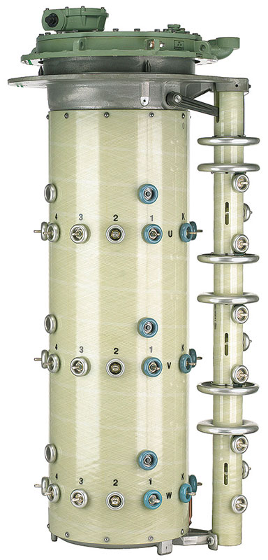
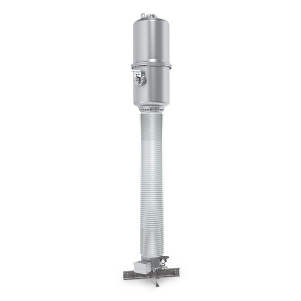
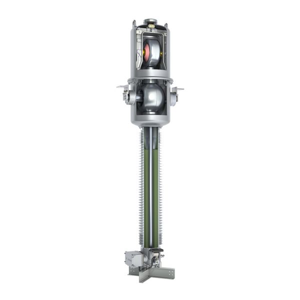
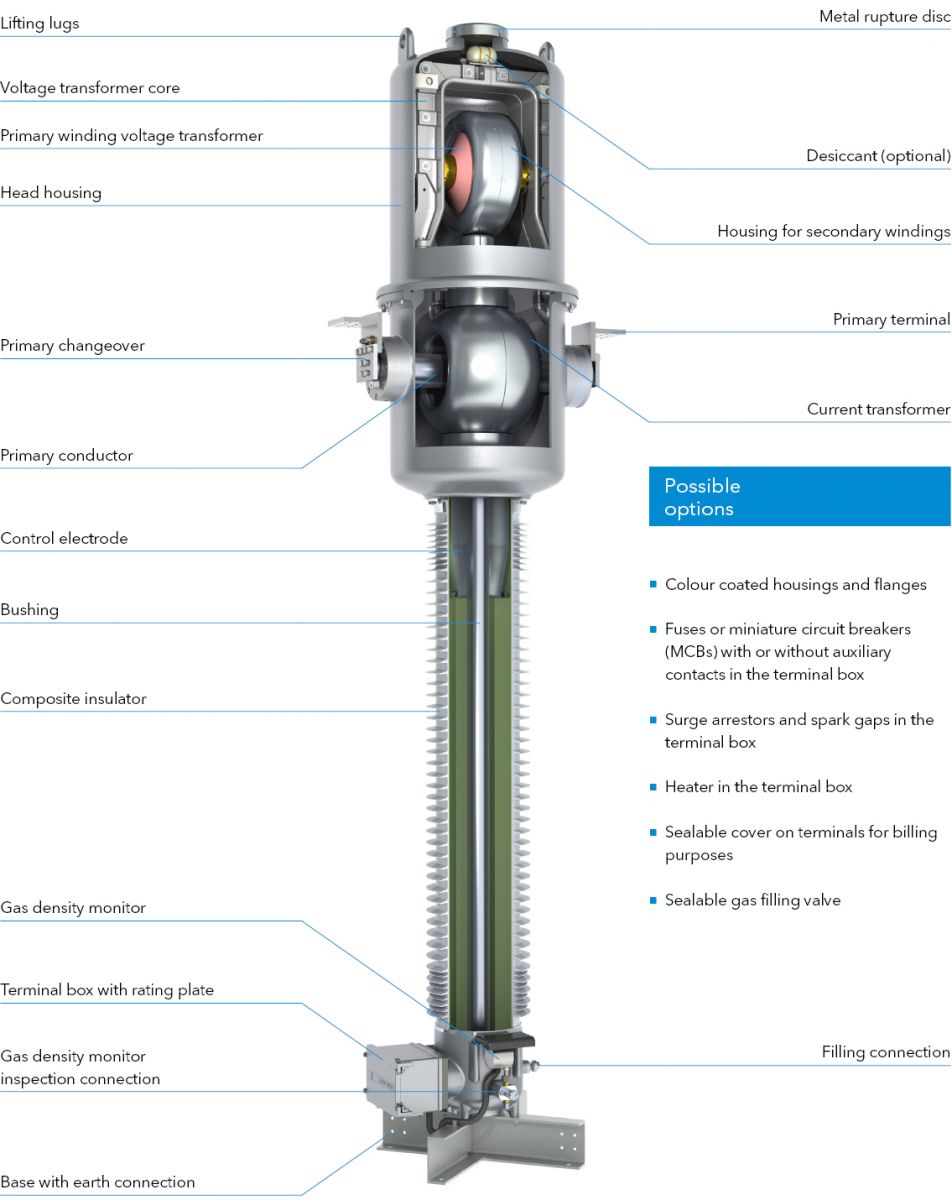
The voltage transformer component is located in the top of the pressure-resistant head housing and the current transformer cores at the bottom. In the current transformer unit, the iron core is set to high-voltage potential and the secondary windings to earth potential. The current transformer cores are fitted in a protective core shell made of massive cast aluminium, which is connected short-circuit proof to the bushing. The secondary outlets are passed through the SF6 /air bushing in the connection terminal box on the base support of the insulator.
The current distribution along the insulator is optimised by a special layout of the control electrode inside the silicone composite insulator.
The housing components consist of helium-tight, corrosion-resistant cast aluminium. All housing components under pressure are individually typetested according to applicable pressure vessel standards.
The SF6 gas density is monitored by a temperature-compensated gas density monitor with alarm contacts. The special design means the function of the gas density monitor can be checked without dismounting it.
A corrosion-resistant metal rupture disc, protected by a metal cover, located at the top of the head housing ensures safe pressure relief in case of error. The generously designed terminal box is equipped with a cover that opens sidewards.
Pure SF6 gas is used for ambient temperatures up to -40°C. The transformer is filled with a mixed gas for lower ambient temperatures up to -60°C.
Advantages of combined
instrument transformers
- Reduced transport costs with one unit instead of two
- Less space needed with just one footprint
- Lower material costs due to a reduced number of supports and fewer primary connections
- Lower installation effort as only one unit has to be installed instead of two
HIGHLIGHTS

Easy
primary changeover
- A clear and easy primary changeover with a ratio of 1:2 or 1:2:4 is available.
- The primary changeover is adjusted with one metal plate at each side of the head only.
- No need to dismount or move the primary connections during adjustment.

Excellent protection
against moisture
- The inner side of the instrument transformer is protected against moisture by means of special sealing rings.
- All housings are designed with a drain-age area to protect the sealing surfaces of the housings against rain. This significantly reduces crevice corrosion.
- The housing elements are connected with special stainless steel screws. They are designed in such a way that no humidity can enter the screw hole.

Installation-friendly
terminal box
- The generously sized terminal box with a cover that can be opened sidewards, is secured with captive screws. It can accommodate terminal blocks, fuses, surge arrestors, additional auxiliary contacts, spark gaps and sealable covers.
- The terminal box is equipped as standard with a blind flange. Cable glands can be installed on request.
- The terminal box has a protected ventilation aperture to prevent condensation.
DESIGN
TECHNICAL DATA

| Type EJGF | 245 | 300 | 330 | 362 | 420 | 550 | ||
|---|---|---|---|---|---|---|---|---|
| Standard | IEC / IEEE | |||||||
| Highest voltage for equipment | kV | 245 | 300 | 330 | 363 | 420 | 550 | |
| Rated power-frequency withstand voltage | kV | 460 | 460 | 460 | 575 | 630 | 680 | |
| Rated lightning impulse withstand voltage | kV | 1050 | 1050 | 1175 | 1175 | 1425 | 1550 | |
| Frequency | Hz | 50 / 60 | ||||||
| Primary rated current | A | ≤ 5000 | ||||||
| Secondary rated current | A | 1 / 5 | ||||||
| Rated short-time thermal current [Ith] | kA / 3s | ≤ 80 | ||||||
| Rated dynamic current [Idyn] | kA | ≤ 200 | ||||||
| Accuracy class CT part | 0.1-3; P; PR; PX; TPS; TPX; TPY; TPZ | |||||||
| Accuracy class VT part | 0.1-3; 3P; 6P | |||||||
| Rated thermal limiting output VT part | VA | ≤ 3000 | ||||||
| Max. simultaneous burden (cl. 0.2) | VA | 300 | ||||||
| Max. number of CT cores | 8 | |||||||
| Max. number of VT windings | 5 | |||||||
| Nominal operating / transport overpressure (20°C) | bar | 4 / 0.5 | ||||||
| Type EJGF | 245 | 300 | 330 | 362 | 420 | 550 | ||
| Height of unit* | A | mm | 4980 | 4980 | 6140 | 6140 | 6500 | 7440 |
| Height to primary terminal* | B | mm | 3375 | 3375 | 4730 | 4730 | 5090 | 5890 |
| Depth of unit including terminal box | C | mm | 845 | 845 | 1088 | 1088 | 1088 | 1088 |
| Depth of unit base | D | mm | 749 | 749 | 1088 | 1088 | 1088 | 1088 |
| Width of unit base | E | mm | 736 | 736 | 1075 | 1075 | 1075 | 1075 |
| Distance between screw holes at base | F | mm | 600 | 600 | 900 | 900 | 900 | 900 |
| Min. creepage distance* | mm | 6700 | 7500 | 8250 | 9050 | 10500 | 13750 | |
| Gross weight, approx.* | kg | 940 | 940 | 1000 | 1000 | 1600 | 1700 | |
| Gas weight, approx.* | kg | 45 | 45 | 58 | 58 | 60 | 63 | |
*with standard composite silicone insulator, creepage distance 25 mm/kV