


JOF (24-550) kV
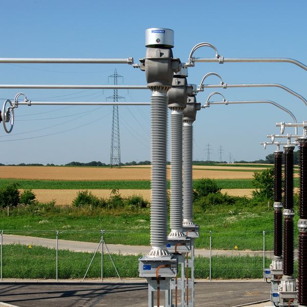
CURRENT TRANSFORMERS | OUTDOOR OPERATION
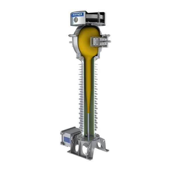
- Oil-paper insulated
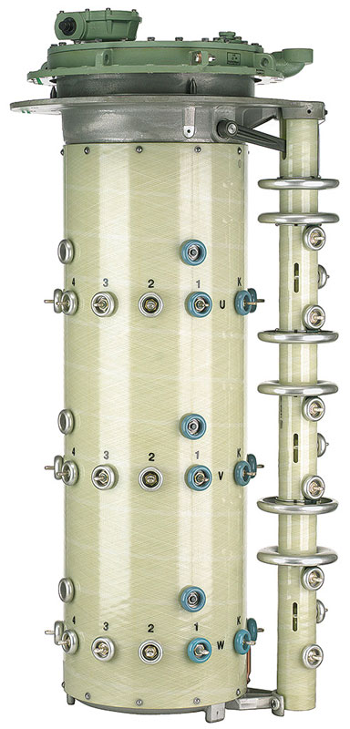
- Simple primary winding changeover
- Explosion-tested casing
- Fine-graded bushing
- Generously-sized terminal box
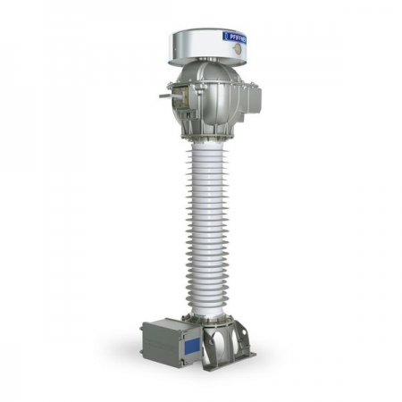
Current transformers type JOF are used in high voltage networks within the 24-550 kV range. They transform high current into standardised values for meters, measuring and protection devices.
GENERAL DESCRIPTION
Current transformers type JOF are used in high voltage networks within the 24-550 kV range. They transform high current into standardised values for meters, measuring and protection devices.
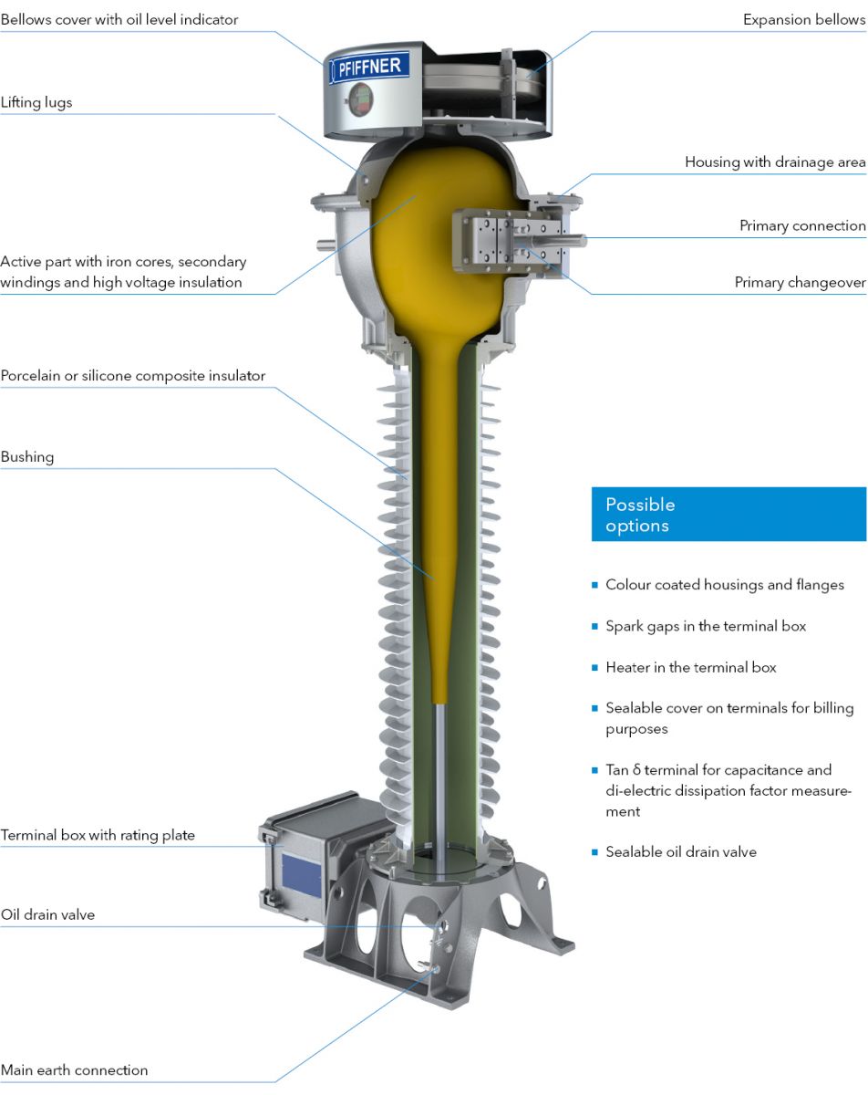
The active part of the current transfor- mer is located in the head housing. Based on customer specifications, the optimum design is calculated and the corresponding head housing is determi- ned.
The high voltage insulation is based on oil-paper technology. High-grade, PCB-free mineral oil is used. The fine graded bushing is inside the insulator.
The expansion bellows made from stainless steel is located above the head housing of the current transformer. This unit acts as volume compensation for the oil in case of temperature variations. The oil level is indicated by a mechanical system in the window of the bellows cover.
All metal housings and flanges are made from a special aluminium alloy. These parts can be colour coated on request.
All current transformers have either a high-quality porcelain or a high-grade silicone composite insulator. Different creepage distances are available according to the different pollution classes, as specified in the standards.
The hermetic sealed housing protects the oil-paper insulation against atmos- pheric influences.
The generously sized terminal box has a cover which can be opened sidewards. This allows easy connection of the secondary cables. The terminal box has a flange without holes by default. Cable glands, circuit diagram and individual safety instructions can be preinstalled on request.
Advantages of
current transformers
- Precise electric field control and prevention of local partial discharges through fine graded bushing
- Higher safety through prevention of subsequent arcing
- High operating safety as there are no active parts in the isolator
- Minimum oil volume through opti- mised design
HIGHLIGHTS

Easy
primary changeover
- A clear and easy primary changeover with a ratio of 1:2 or 1:2:4 is available.
- The primary changeover is adjusted with one metal plate at one side of the head only.
- No need to dismount or move the primary connections during adjustment.

Excellent protection
against moisture
- The inner side of the instrument transformer is protected against moisture by means of special sealing rings.
- All housings are designed with a drain-age area to protect the sealing surfaces of the housings against rain. This significantly reduces crevice corrosion.
- The housing elements are connected with special stainless steel screws. They are designed in such a way that no humidity can enter the screw hole.

Installation-friendly
terminal box
- The generously sized terminal box with a cover that can be opened sidewards, is secured with captive screws. It can accommodate terminal blocks, fuses, spark gaps and sealable covers.
- By default, all terminal boxes have a flange without holes. Cable glands can be preinstalled on request.
DESIGN
TECHNICAL DATA

| Type JOF | 24 | 36 | 72 | 123 | 145 | 170 | 245 | 362 | 420 | 550 | ||
|---|---|---|---|---|---|---|---|---|---|---|---|---|
| Standard | IEC / IEEE | |||||||||||
| Highest voltage for equipment | kV | 24 | 36 | 72.5 | 123 | 145 | 170 | 245 | 362 | 420 | 550 | |
| Rated power-frequency withstand voltage | kV | 50 | 70 | 140 | 230 | 275 | 325 | 460 | 510 | 630 | 680 | |
| Rated lightning impulse withstand voltage | kV | 125 | 170 | 325 | 550 | 650 | 750 | 1050 | 1175 | 1425 | 1550 | |
| Frequency | Hz | 16.7 / 50 / 60 | ||||||||||
| Primary rated current | A | ≤ 4000 | ||||||||||
| Secondary rated current | A | 1 / 5 | ||||||||||
| Rated short-time thermal current [Ith] | kA / 1s | ≤ 63 | ||||||||||
| Rated dynamic current [Idyn] | kA | ≤ 160 | ||||||||||
| Accuracy class | 0.1-3; 0.2S; 0.5S; P; PR; PX; PXR; TPX; TPY; TPZ | |||||||||||
| Max. number of CT cores | 7 | |||||||||||
| Type JOF | 24 | 36 | 72 | 123 | 145 | 170 | 245 | 362 | 420 | 550 | ||
| Height of unit* | A | mm | 1632 | 1632 | 1782 | 2256 | 2532 | 2631 | 3912 | 4440 | 4944 | 5644 |
| Height to primary terminal* | B | mm | 1186 | 1186 | 1336 | 1810 | 2086 | 2185 | 3248 | 3776 | 4280 | 4980 |
| Depth of unit including terminal box | C | mm | 725 | 725 | 725 | 725 | 725 | 725 | 851 | 851 | 851 | 851 |
| Depth of unit base | D | mm | 500 | 500 | 500 | 500 | 500 | 500 | 650 | 650 | 650 | 650 |
| Width of unit base | E | mm | 500 | 500 | 500 | 500 | 500 | 500 | 700 | 700 | 700 | 700 |
| Distance between screw holes at base | F | mm | 450 | 450 | 450 | 450 | 450 | 450 | 600 | 600 | 600 | 600 |
| Min. creepage distance* | mm | 1340 | 1340 | 1950 | 3080 | 3900 | 4394 | 8250 | 10230 | 11600 | 15260 | |
| Approximate weight* | kg | 220 | 220 | 230 | 285 | 295 | 300 | 830 | 800 | 900 | 1000 | |
*with standard composite silicone insulator, creepage distance 25 mm/kV