สินค้า
EOF (24-245) kV
รายละเอียด
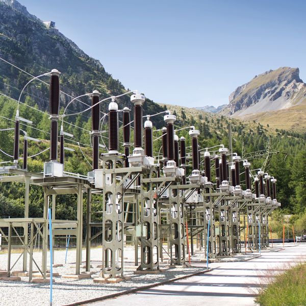
VOLTAGE TRANSFORMERS | OUTDOOR OPERATION
- Oil-paper insulated
- Fine-graded bushing
- Oil level indicator
- Generously-sized terminal box
Voltage transformers type EOF are used in high voltage networks within the 24-245 kV range. They transform high voltage into standardised values for meters, measuring and protection devices.
GENERAL DESCRIPTION
Voltage transformers type EOF are used in high voltage networks within the 24-245 kV range. They transform high voltage into standardised values for meters, measuring and protection devices.
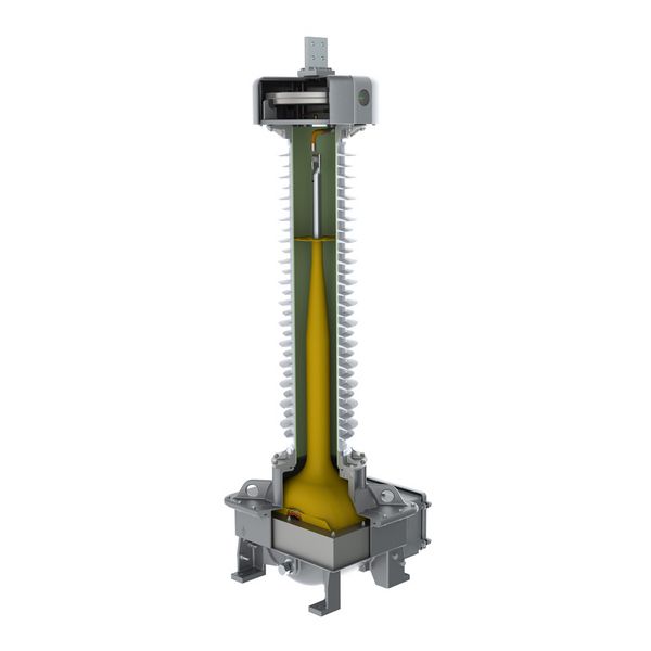
The active part of the voltage transformer is located in the foot housing. The high voltage insulation is implemented in oil-paper technology. To achieve this, a high quality PCB-free mineral oil is used. The fine graded bushing is inside the insulator.
The expansion system is located in the head of the voltage transformer. This unit acts as volume compensation for the oil in case of temperature variations. For voltage transformers of 24-72 kV, a highly flexible, temperature-resistant membrane made from fluoroelastomers (VITON®) is used. Voltage transformers >72 kV have an expansion cell made of stainless steel. The oil level is indicated by a mechanical system in the window of the bellows cover.
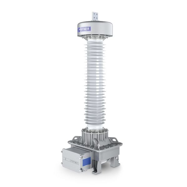
All metal housings and flanges are made from a special aluminium alloy. These parts can be colour coated on request.
All voltage transformers have either a high-quality porcelain or a high-grade silicone composite insulator. Different creepage distances are available according to the different pollution classes, as specified in the standards.
The hermetic sealed housing protects the oil-paper insulation against atmospheric influences.
The generously sized terminal box has a cover which can be opened sidewards. This allows easy connection of the secondary cables. The terminal box has a flange without holes by default. Cable glands, circuit diagram and individual safety instructions can be preinstalled on request.
Advantages of
inductive voltage transformers
- Protection of the secondary winding from transient overvoltages in the high-voltage network through capacitively coupled shielding
- Protection against occurring ferroresonance through low operating inductance in the iron core
- High operating safety as there are no active parts in the insulator
- Minimum oil volume through optimised design
HIGHLIGHTS

Fine
graded bushing
- The fine graded bushing is designed to ensure an optimum distribution of the electric field.
- The bushing is fixed in a way, that it is short-circuit-safe and secondary arcs are prevented.

Excellent protection
against moisture
- The inner side of the instrument transformer is protected against moisture by means of special sealing rings.
- All housings are designed with a drain-age area to protect the sealing surfaces of the housings against rain. This significantly reduces crevice corrosion.
- The housing elements are connected with special stainless steel screws. They are designed in such a way that no humidity can enter the screw hole.

Installation-friendly
terminal box
- The generously sized terminal box with a cover that can be opened sidewards, is secured with captive screws. It can accommodate terminal blocks, fuses, surge arrestors, additional auxiliary contacts, spark gaps and sealable covers.
- By default, all terminal boxes have a flange without holes. Cable glands can be preinstalled on request.
- An additional terminal box can be supplied on request.
DESIGN

TECHNICAL DATA

| Type EOF | 24 | 36 | 72 | 123 | 145 | 170 | 245 | ||
|---|---|---|---|---|---|---|---|---|---|
| Standard | IEC / IEEE | ||||||||
| Highest voltage for equipment | kV | 24 | 36 | 72.5 | 123 | 145 | 170 | 245 | |
| Rated power-frequency withstand voltage | kV | 50 | 70 | 140 | 230 | 275 | 325 | 460 | |
| Rated lightning impulse withstand voltage | kV | 125 | 170 | 325 | 550 | 650 | 750 | 1050 | |
| Frequency | Hz | 16.7 / 50 / 60 | |||||||
| Accuracy class | 0.1-3; 3P; 6P | ||||||||
| Rated thermal limiting output | VA | ≤ 1500 | ≤ 3000 | ||||||
| Max. simultaneous burden (cl. 0.2) | VA | 200 | 300 | ||||||
| Max. number windings | 5 | ||||||||
| Type EOF | 24 | 36 | 72 | 123 | 145 | 170 | 245 | ||
| Height of unit* | A | mm | 1107 | 1107 | 1430 | 2116 | 2392 | 2581 | 3507 |
| Height to primary terminal* | B | mm | 1027 | 1027 | 1350 | 1976 | 2252 | 2441 | 3206 |
| Depth of unit including terminal box | C | mm | 526 | 526 | 526 | 710 | 710 | 730 | 938 |
| Depth of unit base | D | mm | 360 | 360 | 360 | 500 | 500 | 500 | 660 |
| Width of unit base | E | mm | 360 | 360 | 360 | 520 | 520 | 520 | 660 |
| Distance between screw holes at base | F | mm | 310 | 310 | 310 | 450 | 450 | 450 | 600 |
| Min. creepage distance* | mm | 950 | 950 | 1860 | 3080 | 3900 | 4394 | 6160 | |
| Approximate weight* | kg | 115 | 115 | 125 | 305 | 330 | 335 | 350 | |
*with standard composite silicone insulator, creepage distance 25 mm/kV